Small-Scale Subsonic Wind Tunnel
Independent Capstone | Solo Design, Build and Test | Autodesk Inventor | FDM Printing | Mar–May 2026
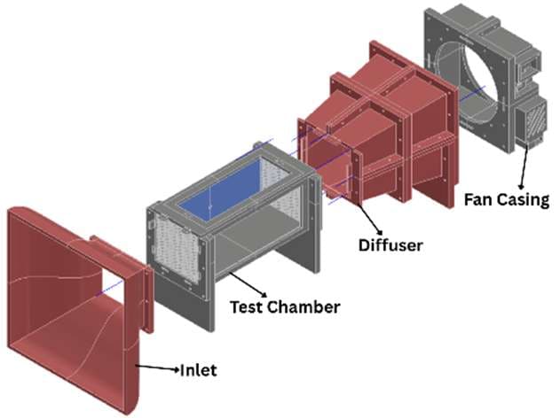
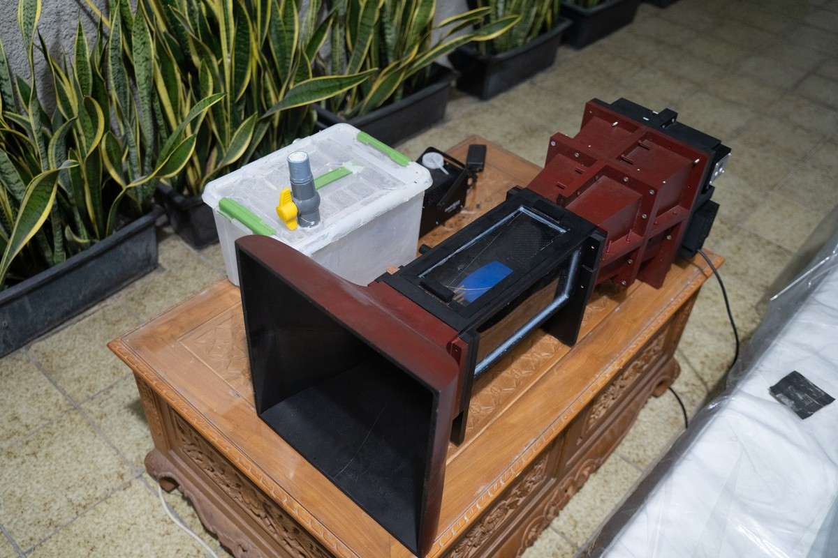
Wind tunnels in Indonesia sit in a handful of institutions, so most engineering students, me included, never test anything in one. I set out to build a desktop tunnel that students could afford to design and build; about a metre long, at least 7 m/s wind velocity through the test section, under Rp 2.5 million. This wind tunnel is purely for educational purposes, for students to understand how air flows through object.
I was building every part alone, on a BambuLab X1 3D Printer with a 257 mm bed, and in a wind tunnel every part affects the flow. Most of the real problems only showed up once the parts existed and tested.
The planned 20 × 20 cm test section was as wide as the 225 mm fan, leaving the diffuser with nothing to expand into and its inlet wouldn't fit the print bed even in four pieces.
Cut the test section to 15 × 15 cm and re-derived the geometry from the contraction ratio: 7.1, inside the recommended 6-9 ratio, on a fifth-order polynomial contour.
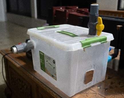
Water vapour, the original smoke source, was far too thin for the volume of air a 225 mm fan moves.
Switched to a fog machine running a glycerine-aquadest mix.
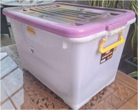
The 82 L plenum lost pressure and heat so fast that the smoke settled on the floor of the box.
Rebuilt it at 22 L. When that was still too thin, shortened the delivery hose and moved the valve.
The short copper tubes for the smoke rake slipped in the bender and kinked: they folded flat at the bend instead of curving.
Printed a PLA clamping block for the die that pins the tube, giving a clean, even bend.
The drilled reservoir holes choked the smoke on its way into the rake.
Opened them into one rectangular slot. The tubes were already held by the rake mount, so the holes weren't structural.
The black-painted test chamber reflected the LED light and washed out the streamlines.
Lined the walls and floor with velvet fabric, which absorbs the light and gives a dark background with significantly reduced glare.
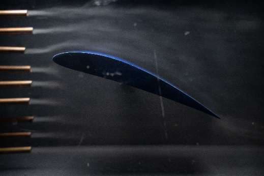
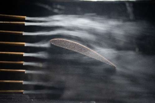
Six of seven specifications met. The tunnel draws clear, steady streamlines around an airfoil at about 80 % fan speed, runs on 65 W from a household socket, and is now in use as a university fluid mechanics lab instrument. It came in 3.6 % over budget because trial and error resulted in more filament used. Validation was visual: 7.42 m/s is calculated from the fan's rated flow and the honeycomb blockage and measuring it with a pitot tube is the next step.