Multi-Element Side Wings and Rear Diffuser
Bachelor's Thesis | UIRT-03 Formula Student Chassis | Jan–Jun 2026
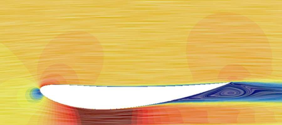
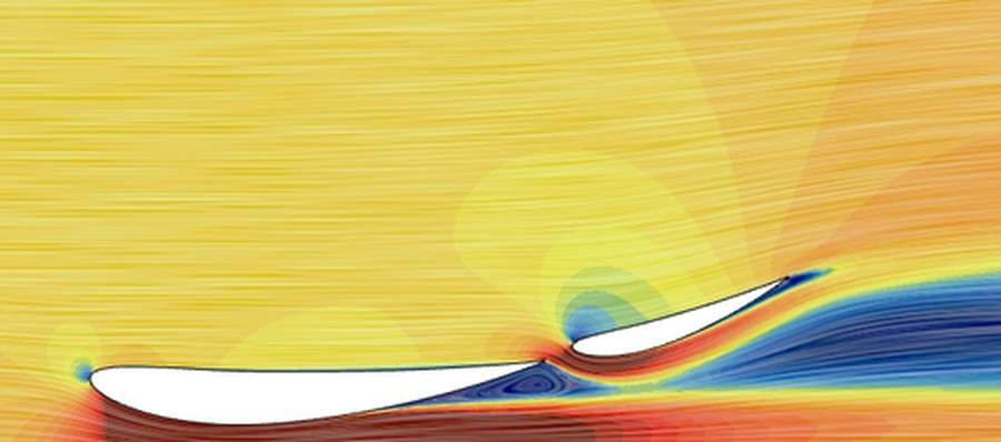
Formula Student is won in tight corners at 40–60 km/h, where downforce matters more than top speed. Our team designed its side wings by trial-and-error iterations. I wanted to leave the next generation a repeatable, numbers-based method instead.
- The bare UIRT-03 chassis made lift, not downforce: −20.55 N at 60 km/h.
- Could a ground-effect package alone (three-element side wings and a rear diffuser) turn that around, and could it replace a front and rear wing altogether?
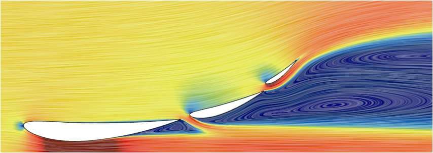
Adding a third element made the wing worse: my first three element sweep peaked at CL = 1.730, below the two-element best of 3.143.
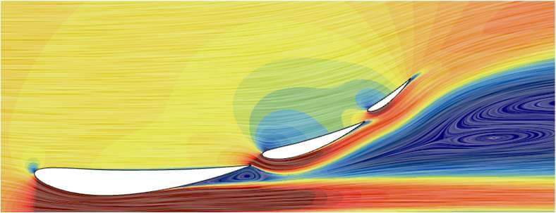
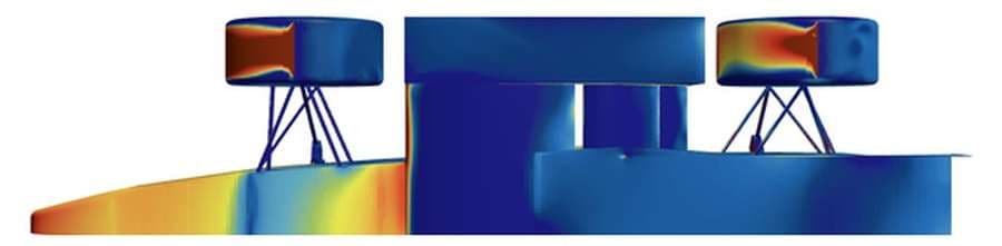
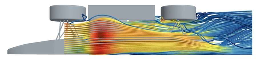
The contours showed flow failing to reach the downstream elements. My initial sweep had been too narrow (0-3 % overlap); widening it to 0-6 % found CL = 4.044 (+134 %) at 5 % overlap and spacing, same airfoils. Cp plots traced the gain to the main and second elements.
Fine polyhedral meshes ran past the workstation's 64 GB of RAM.
Switched to a trimmed hex-dominant mesh aligned with the freestream, and a symmetry plane that halved the 3D cell count; spending the saving on refinement around the wings.
The two-element grid study didn't reach mesh independence: the finest mesh came in 10.3% below the chosen one, though both converged to 10−5.
Every design in each sweep was meshed with the same settings, so comparing them is fair, but the exact CL values carry that uncertainty (about 7 % in 3D).
Lowering the side wings 10 mm for more ground effect cut the gain from 128.9 N to 116.8 N.
Read it as separation rather than ground effect and kept the standard ride height for the final Maximum Area design.
The 20° diffuser added 40.8 N of downforce over the bare chassis. The Maximum Area side wings added 128.9 N for 6.2 N more drag. On its own, it's unlikely to replace a full front-and-rear wing package at 60 km/h. Whether it's enough depends on the team's lap-time targets. Each was simulated on its own, so testing them together is the next step. The team now has a step-by-step method for multi-element side wings, from airfoil choice through slot geometry to placement on the car.